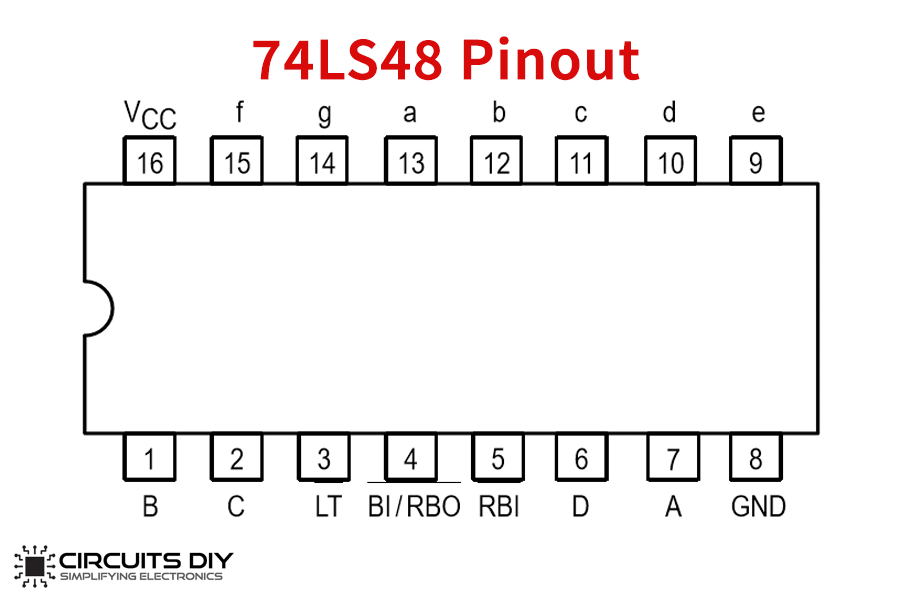
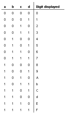
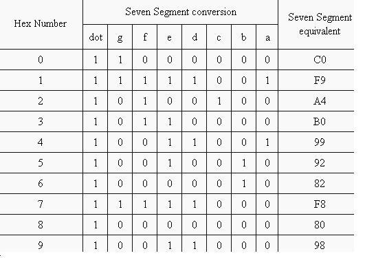
We want to design a circuit which will take four binary inputs and print hexadecimal number equivalent to that binary number. This circuit is called seven segment hex decoder. There are 16 digits in hexadecimal number which are 0-9 numbers and A-F alphabets. We will use common cathode display. I was trying to display 7-segment LED on MDA-8086 kit, but I am stuck at calculating the hexadecimal values for respective digits. I have the code with me, but I don't understand how it actually works. For example, 0 is represented by hexadecimal value 0xc0 I guess. I am wondering, how the values have been calculated here? Seven segment display is the most common device used for displaying digits and alphabet. You can see the Seven Segment Display devices in TV shows counting down to ‘0’. Use of LEDs in seven segment displays made it more popular. The binary information can be displayed in the form of decimal using this seven segment display. The hexadecimal to 7 segment encoder has 4 bit input and 7 output. Depending upon the input number, some of the 7 segments are displayed. The seven segments are represented as a,b,c,d,e,f,g. A high on one of these segements make it display. For example to write 1 we need to display segments b and C. The 7 segment display also has a decimal. Our 4-digit seven-segment controller will take a clock and four characters (4-bit each) as inputs, and will write the seven-segment control signals as well as the four anode signals to display all four characters simultaneously. The figure below shows a block diagram of a possible implementation of this controller.
7 Segment Hex Code Color
A common but useful component
- 4,870 views
- 0 comments
- 3 respects
Components and supplies
| × | 1 | |
| × | 1 |
Apps and online services
About this project
Posted on January 8, 2017 by electromaniaweb
The main advantage of light emitting diodes is that because of their small die size, several of them can be connected together within one small and compact package producing what is generally called a 7-segment Display.
The 7-segment display, also written as “seven segment display”, consists of seven LEDs (hence its name) arranged in a rectangular fashion as shown. Each of the seven LEDs is called a segment because when illuminated the segment forms part of a numerical digit (both Decimal and Hex) to be displayed. An additional 8th LED is sometimes used within the same package thus allowing the indication of a decimal point, (DP) when two or more 7-segment displays are connected together to display numbers greater than ten.
Two types of SSD’s are available.
- Common cathode Seven segment display

2. Common anode Seven segment display.
For now we will use a common anode seven segment display.
ASSEMBLING THE CIRCUIT.
- Firstly we will start by connecting the first pin on the seven segment display to the 2nd pin in the arduino. In likewise fashion we will connect the second to the third pin slot in arduino.
- Now comes the tricky part, we have to connect the third pin on the seven segment display to the pin on the opposite side of it. And then connect them both to the ground slot in the arduino.
- Now in like wise fashion we will keep joining the pin in the seven segment display to the arduino till pin 9 of the arduino.
We are all done with assembling the circuit.
Now there is an interesting breadboarding technique that can be used in this particular project. Using the same code mentioned above we can use two and up to four, Seven segment display countdown. Only con is that we will require an inexplicable amount of jumper wires.
I will show you how I did it for two SSD’s you can try on for as many as you like if you have those many jumper wires and breadboard.
What I did here was to connect the pin wire of the arduino to a slot in the breadboard and then join that slot to the two SSD’s simultaneously so that both of the SSD’s get the same common from the code and perform the same function.

Here you can clearly see what I did. But this was just to brush up your basic breadboarding skills and to be honest becomes very tiring and messy with so many wires.
Code
Author
AJ-Explains-It-All
- 7 projects
- 7 followers
7 Segment Hex Code Symbols
Published on
December 21, 2018Members who respect this project
and 2 others

7 Segment Hex Code Converter
See similar projectsyou might like
